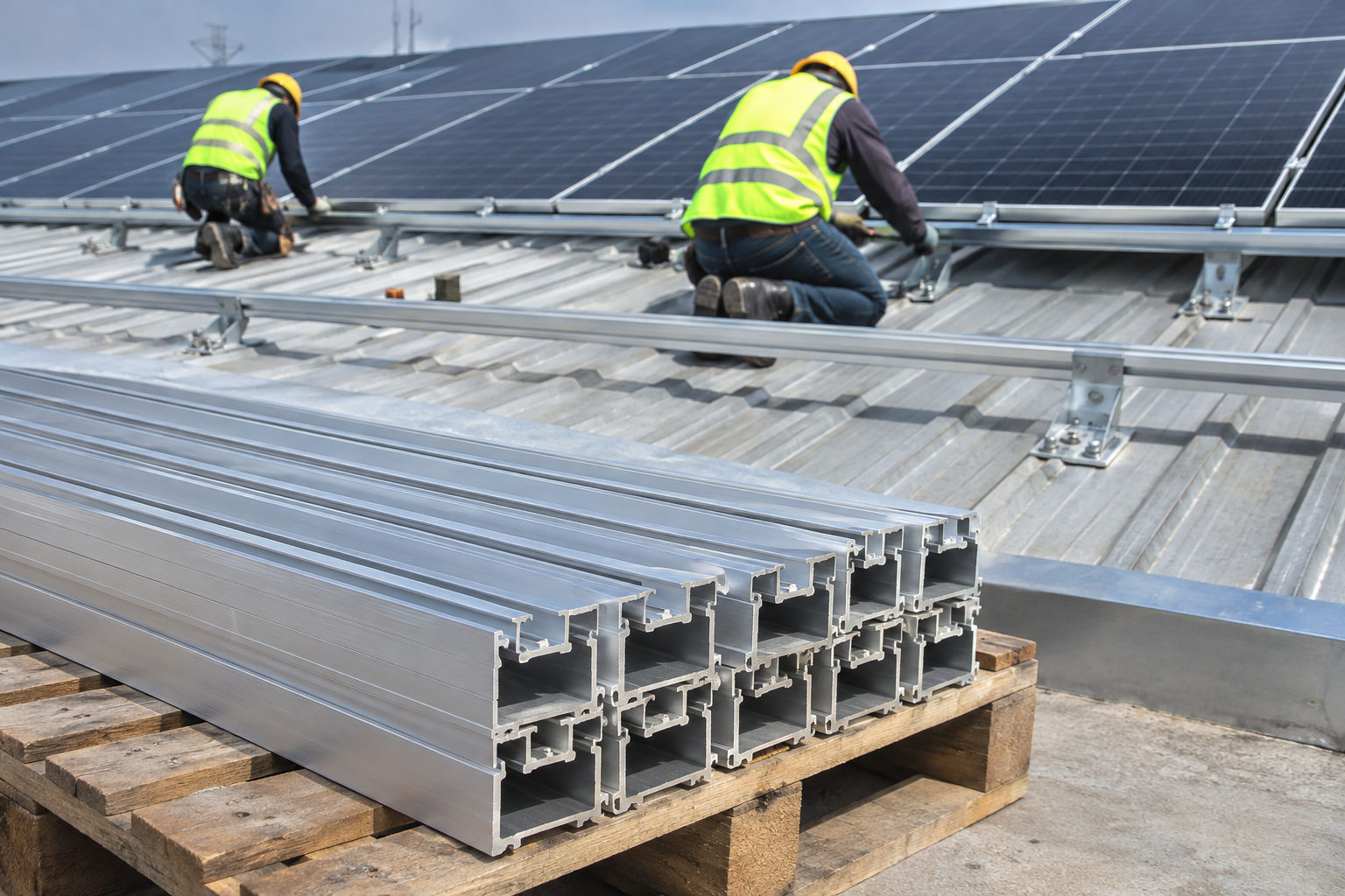
Solar rail and clamp selection is an interface problem as well as a structural one. The rail must suit the support layout, and the clamp must suit both the module and the rail channel. SolarNova supplies SN- mounting materials for project procurement. Use the listed profiles and component specifications to define an RFQ, then confirm the complete assembly against the project design and module installation instructions.
Start with the module and array layout
Collect the exact module datasheet and installation manual, including dimensions, weight, frame geometry and permitted clamp zones. Record portrait or landscape orientation, row arrangement and maintenance access. A change in module size can move the required rail positions and alter the number of clamps, splices and supports.
Frame height is a necessary input for framed modules, but it is not a complete compatibility check. The clamp contact area, frame shape and approved fixing locations also matter. Frameless laminates require their own compatible retention method. Do not substitute a framed-module clamp simply because it appears able to grip the glass edge.
Choose the rail by its complete section
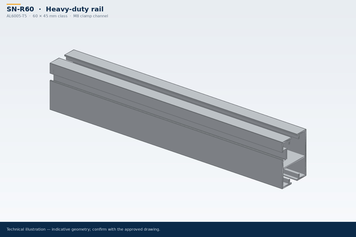
Compare profile drawings rather than nominal height alone. Rail geometry, material, support conditions and connection details affect performance. A heavier-looking rail is not automatically suitable for a longer span, and the distance between supports cannot be selected independently of project loading and the attachment design.
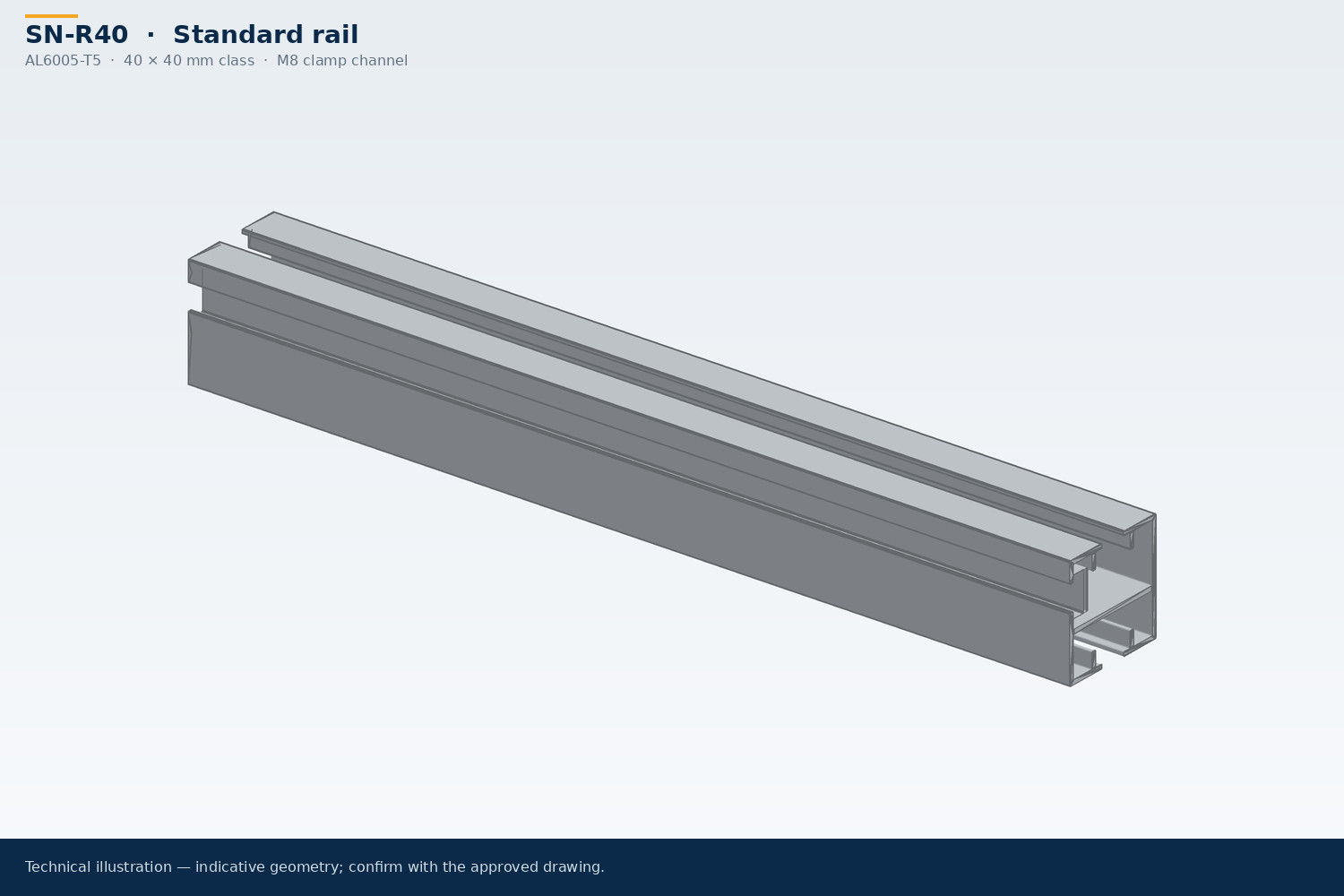
The SN-R40 standard rail lists an AL6005-T5, 40 × 40 mm class profile. Its published span is explicitly indicative and subject to loads and profile calculation. Treat that figure as preliminary procurement information. Request confirmation of the selected drawing and design basis before using a span in construction documents.
Coordinate rail lengths and splices
Develop a cutting and splice plan from the final array layout. Consider handling, roof access, transport and the locations where rails connect to supports. Long rails can reduce some joints while introducing different handling and packing constraints. Short rails need an attachment method appropriate to the roof and module arrangement.
Ask for the splice drawing, fastener schedule and any restrictions on splice position. Thermal movement may require gaps or separated rail runs according to the system instructions. Include those details in the bill of materials and installation package so the field team does not improvise the layout from the shipped lengths alone.
Match clamps to the rail channel
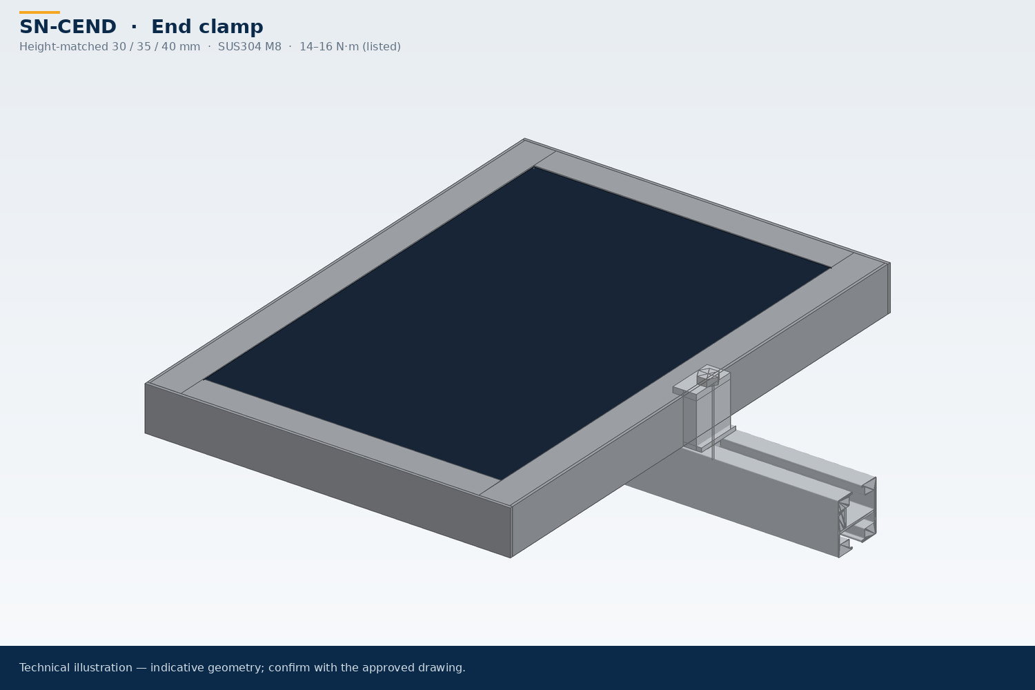
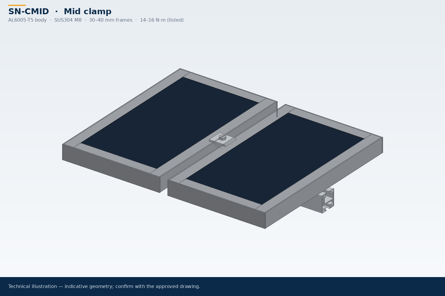
Mid clamps hold neighboring modules, while end clamps serve array edges. Quantities therefore depend on the actual row arrangement, not only the module count. Confirm the selected clamp’s frame-height range, contact geometry and connection to the rail. An adjustable or universal description does not mean a clamp fits every module.
Thread size alone does not establish channel compatibility. Check the bolt or nut seating, engagement, adjustment travel and complete connection stack. The SN-R40 page describes an M8 channel interface and explicitly calls for verification of slot and bolt engagement. Send interface drawings when matching new clamps to existing rails from another source.
Verify torque, bonding and exposure
Use the confirmed tightening instructions for the exact module, clamp and fastener combination. A torque value from an unrelated assembly should not become a site instruction. Ask how installers should verify correct seating and identify any required inspection records. Include replacement or spare fasteners in the purchasing scope where appropriate.
Bonding also needs a coordinated design. A metal-to-metal joint should not automatically be assumed to provide the required electrical continuity. Where clips, pins or piercing plates are used, confirm compatible surfaces, installation details and the complete bonding path. Material and finish selection should reflect the environment and the project’s corrosion requirements.
Order a coordinated component schedule
Request a bill of materials tied to a drawing revision, with rail lengths, splice quantities, mid and end clamps, attachment parts and fasteners clearly separated. Ask the supplier to identify substitutions, exclusions and any dimensional assumptions. A sample interface check can help resolve fit questions, but it does not replace structural verification.
Keep the product references consistent across the drawing, quotation and packing list. MOQ, samples, packaging and delivery are confirmed for the selected SN- products in the quotation. Contact us for payment terms; commercial terms are confirmed in the written quotation.
Contact SolarNova with your module manual, layout and rail interface requirements to request a coordinated rail-and-clamp quotation.